


Product
PRODUCTS

SCB13 Dry-type Transformer
Category:
Keywords:
SCB13 Dry-type Transformer
dry-type power transformer
dry-type power transformer
dry-type power transformer
dry-type power transformer
dry type transformer
1. Product Introduction:
This series of epoxy resin cast dry-type transformer materials are of high quality and scientifically formulated, produced strictly according to processes using excellent production and testing equipment. The product features high reliability and long service life. Depending on different usage environments, different protective shell levels can be configured or no shell at all. Suitable for important or special environments such as high-rise buildings, commercial centers, airports, tunnels, chemical plants, nuclear power plants, ships, etc.
2. Standards:
2.1 IEC60076-11 Dry-type power transformers
2.2 GB/T1094.1 Power transformers
2.3 GB/T1094.11 Dry-type power transformers
2.4 GB/T10228 Technical parameters and requirements for dry-type power transformers
2.5 JB/T10088 Sound level of power transformers rated 6kV~500kV
2.6 GB20052-2020 Energy efficiency limits and energy efficiency grades for power transformers
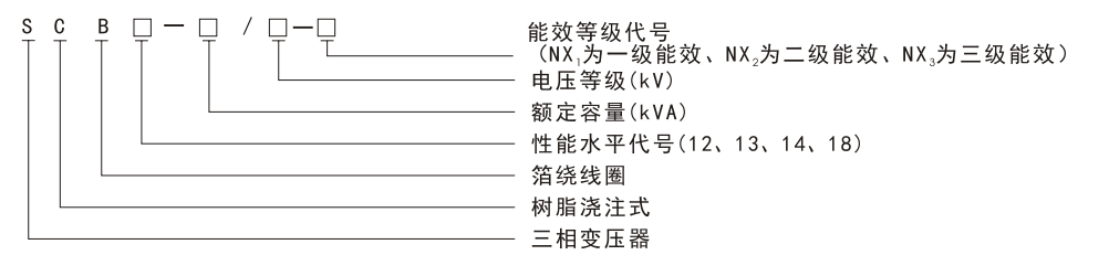
3. Model and Meaning:
4. Performance Features:
4.1 Safe, fireproof, pollution-free, can operate directly at the load center.
4.2 Uses Swiss T+M technology, with high mechanical strength, strong short-circuit resistance, low partial discharge, good thermal stability, high reliability, and long service life.
4.3 Low loss, low noise, significant energy-saving effect, maintenance-free.
4.4 Good heat dissipation performance, strong overload capacity, capacity can be increased when forced air cooling is applied.
4.5 Good moisture resistance, suitable for operation in high humidity and other harsh environments.
4.6 Equipped with a complete temperature monitoring and protection system. Uses an intelligent signal temperature control system that can automatically monitor and cyclically display the operating temperature of each of the three-phase windings, automatically start and stop fans, and has alarm and trip function settings. 4.7 Compact size, light weight, small footprint, low installation cost. 4.8 Equipped with remote monitoring function to grasp the equipment operating status in real time.
5. Structural Features:
5.1 The high-voltage winding conductor uses high conductivity oxygen-free copper foil, with inter-turn insulation made of F-class insulation material. Both inside and outside of the winding use imported glass mesh boards as the framework. The copper foil along with the turn insulation is programmed once on a high-voltage foil winding machine, controlled by a microcomputer with laser positioning. The lead wires are automatically welded by argon arc welding, wound in segments, then placed into a mold and cast with resin containing fillers under vacuum.
5.2 The low-voltage winding uses copper foil of the same height as the low-voltage winding, wound on a low-voltage foil winding machine together with F-class turn insulation. During winding, the winding lead is automatically welded and led out by copper busbars using argon arc welding. Cooling air channels are formed by inserting support bars in the middle of the winding, and the ends are sealed with resin and cured.
5.3 The core uses high-quality grain-oriented cold-rolled silicon steel sheets, with 45-degree full miter joints and yoke perforation structure to ensure low no-load loss. The core clamping uses laser-cut steel plate bent clamp structure, the core column is tied with insulating tape, upper and lower clamps use an internal pull plate structure. The core surface is sealed with a special resin process, which increases structural strength and clamping force while reducing noise.
Technical Parameters of 10kV Level SCB Series Dry-type Transformer
|
Transformer |
High Voltage (kV |
High Voltage Tap Range (%) |
Low Voltage (kV |
Rated |
Connection Group Number |
No-load Loss (W) |
Load Loss (W) |
No-load |
Noise |
Short Circuit |
Gauge |
Main Unit (excluding enclosure) |
Enclosure |
||||
|
SCB12 |
SCB13 |
SCB12 |
SCB13 |
Overall Dimensions Length×Width×Height (m |
Weight |
Overall Dimensions |
Weight |
||||||||||
|
125 |
6 |
;5 ;2× 2.5 |
0.4 |
50 |
Dyn11 Yyn0 |
375 |
335 |
1850 |
1660 |
1.3 |
58 |
4 |
550×550 |
920×610×1120 |
685 |
500×1150×2200 |
230 |
|
160 |
430 |
385 |
2130 |
1910 |
1.3 |
58 |
550×550 |
950×610×1120 |
735 |
1500×1150×2200 |
230 |
||||||
|
200 |
495 |
445 |
2530 |
2270 |
1.1 |
58 |
660×660 |
990×720×1150 |
820 |
1500×1150×2200 |
230 |
||||||
|
250 |
575 |
515 |
2760 |
2480 |
1.1 |
58 |
660×660 |
1030×720×1180 |
960 |
1500×1150×2200 |
230 |
||||||
|
315 |
705 |
635 |
3470 |
3120 |
1 |
60 |
660×660 |
1050×720×1210 |
1080 |
1500×1150×2200 |
230 |
||||||
|
400 |
785 |
705 |
3990 |
3590 |
1 |
60 |
660×660 |
1060×720×1270 |
1330 |
1600×1250×2200 |
250 |
||||||
|
500 |
930 |
835 |
4880 |
4390 |
1 |
62 |
660×820 |
1110×880×1340 |
1480 |
1600×1250×2200 |
250 |
||||||
|
630 |
1040 |
935 |
5960 |
5360 |
0.85 |
62 |
6 |
660×820 |
1240×880×1300 |
1530 |
1800×1450×2200 |
280 |
|||||
|
800 |
1210 |
1090 |
6960 |
6260 |
0.85 |
64 |
660×820 |
1320×880×1350 |
1840 |
1800×1450×2200 |
280 |
||||||
|
1000 |
1410 |
1270 |
8130 |
7310 |
0.85 |
64 |
660×820 |
1360×880×1460 |
2320 |
1800×1450×2200 |
280 |
||||||
|
1250 |
1670 |
1500 |
9690 |
8720 |
0.85 |
65 |
820×820 |
1430×880×1520 |
2530 |
1900×1450×2200 |
320 |
||||||
|
1600 |
1960 |
1760 |
11700 |
10500 |
0.85 |
66 |
h070×1070 |
1470×1130×1690 |
3010 |
1950×1500×2200 |
350 |
||||||
|
2000 |
2440 |
2190 |
14400 |
13000 |
0.7 |
66 |
070×1070 |
1510×1130×1770 |
3540 |
2000×1500×2200 |
350 |
||||||
|
2500 |
2880 |
2590 |
17100 |
15400 |
0.7 |
71 |
h070×1070 |
1560×1130×1900 |
4190 |
2300×1600×2200 |
400 |
||||||
|
Transform |
High Voltage |
High Voltage Tap |
Low Voltage (kV |
Rated |
Connection Group Number |
No-load Loss (W) |
Load Loss (W) |
No-load |
Noise |
Short Circuit |
Gauge |
Main Unit (excluding enclosure) |
Enclosure |
||||
|
SCB14 |
SCB18 |
SCB14 |
SCB18 |
Overall Dimensions Length×Width×Height (m |
Weight |
Overall Dimensions |
Weight |
||||||||||
|
125 |
6 |
52× 2.5 |
0.4 |
50 |
Dyn11 Yyn0 |
320 |
270 |
1665 |
1665 |
1.3 |
58 |
4 |
550×550 |
960×610×830 |
780 |
500×1150×2200 |
230 |
|
160 |
365 |
310 |
1915 |
1915 |
1.3 |
58 |
550×550 |
990×610×850 |
900 |
1500×1150×2200 |
230 |
||||||
|
200 |
420 |
360 |
2275 |
2275 |
1.1 |
58 |
660×660 |
1020×720×870 |
1000 |
1500×1150×2200 |
230 |
||||||
|
250 |
490 |
415 |
2485 |
2485 |
1.1 |
58 |
660×660 |
1060×720×920 |
1160 |
1500×1150×2200 |
230 |
||||||
|
315 |
600 |
510 |
3125 |
3125 |
1 |
60 |
660×660 |
060×720×960 |
1220 |
1500×1150×2200 |
230 |
||||||
|
400 |
665 |
570 |
3590 |
3590 |
1 |
60 |
660×660 |
1060×720×1040 |
1430 |
1600×1250×2200 |
250 |
||||||
|
500 |
790 |
670 |
4390 |
4390 |
1 |
62 |
660×820 |
1130×880×1100 |
1620 |
1600×1250×2200 |
250 |
||||||
|
630 |
885 |
750 |
5365 |
5365 |
0.85 |
62 |
6 |
660×820 |
1340×880×1100 |
1930 |
1800×1450×2200 |
280 |
|||||
|
800 |
1035 |
875 |
6265 |
6265 |
0.85 |
64 |
660×820 |
1350×880×1160 |
2250 |
1800×1450×2200 |
280 |
||||||
|
1000 |
1205 |
1020 |
7315 |
7315 |
0.85 |
64 |
660×820 |
1400×880×1220 |
2580 |
1800×1450×2200 |
280 |
||||||
|
1250 |
1420 |
1205 |
8720 |
8720 |
0.85 |
65 |
820×820 |
1460×880×1300 |
3080 |
1900×1450×2200 |
320 |
||||||
|
1600 |
1665 |
1415 |
10555 |
10555 |
0.85 |
66 |
1070×1070 |
1520×1130×1370 |
3700 |
1950×1500×2200 |
350 |
||||||
|
2000 |
2075 |
1760 |
13005 |
13005 |
0.7 |
66 |
1070×1070 |
1610×1130×1510 |
4300 |
2000×1500×2200 |
350 |
||||||
|
2500 |
2450 |
2080 |
15445 |
15445 |
0.7 |
71 |
1070×1070 |
1620×1130×1590 |
5130 |
2300×1600×2200 |
400 |
||||||
Technical Parameters of 10KV Level SC Station Dry-type Transformer Series
|
Transform |
High Voltage |
High Voltage Tap Range (%) |
Low Voltage |
Rated Frequency (Hz) |
Connection Group |
No-load Loss (W) |
Load Loss (W) |
No-load Current: (%) |
Noise |
Short Circuit |
Gauge |
Main Unit (excluding enclosure) |
Enclosure |
||||
|
SCB12 |
SCB13 |
SCB12 |
SCB13 |
Overall Dimensions |
Weight (kg |
Overall Dimensions |
Weight |
||||||||||
|
30 |
6 |
5 |
0.4 |
50 |
Dyn11 Yyn0 |
150 |
135 |
710 |
640 |
2 |
54 |
4 |
400×350 |
600×400×570 |
300 |
1200×1000×2200 |
180 |
|
50 |
215 |
195 |
1000 |
900 |
2 |
54 |
400×350 |
600×400×640 |
330 |
1200×1000×2200 |
180 |
||||||
|
80 |
295 |
265 |
1380 |
1240 |
1.5 |
55 |
400×400 |
720×500×770 |
500 |
1200×1000×2200 |
180 |
||||||
|
100 |
320 |
290 |
1570 |
1410 |
1.5 |
55 |
400×400 |
730×500×790 |
560 |
1200×1000×2200 |
180 |
||||||
Note: Due to continuous product improvements, the data provided in this sample is for reference only; please contact our company promptly for new dimensions.
Technical Parameters of 20KV Grade SCB Series Dry-type Transformer
|
Transform |
High Voltage |
High Voltage Tap Range (%) |
Low Voltage |
Rated |
Connection Group Number |
No-load |
Load |
No-load Current (%) |
Noise |
Short Circuit |
Gauge |
Main Unit (excluding enclosure) |
Enclosure |
||
|
Overall Dimensions |
Weight |
Overall Dimensions |
Weight |
||||||||||||
|
100 |
20 |
5 |
0.4 |
50 |
Dyn11 YynO |
432 |
1990 |
1.8 |
55 |
6 |
660×660 |
1130×720×1210 |
700 |
1600×1250×2200 |
250 |
|
160 |
536 |
2470 |
1.5 |
58 |
660×660 |
1150×720×1230 |
800 |
1600×1250×2200 |
250 |
||||||
|
200 |
584 |
2940 |
1.5 |
58 |
660×660 |
1200×720×1270 |
920 |
1800×1450×2200 |
280 |
||||||
|
250 |
672 |
3420 |
1.3 |
58 |
820×820 |
1270×880×1300 |
1050 |
1800×1450×2200 |
280 |
||||||
|
315 |
776 |
4080 |
1.3 |
60 |
820×820 |
1300×880×1340 |
1200 |
1800×1450×2200 |
280 |
||||||
|
400 |
920 |
4840 |
1.1 |
60 |
820×820 |
1310×880×1380 |
1430 |
1800×1450×2200 |
280 |
||||||
|
500 |
1080 |
5790 |
1.1 |
62 |
820×820 |
1350×880×1450 |
1600 |
2000×1600×2200 |
350 |
||||||
|
630 |
1220 |
6840 |
1 |
62 |
820×820 |
1470×880×1500 |
1950 |
2000×1600×2200 |
350 |
||||||
|
800 |
1400 |
8260 |
1 |
64 |
820×820 |
1500×880×1550 |
2350 |
2000×1600×2200 |
350 |
||||||
|
1000 |
1660 |
9780 |
0.85 |
64 |
1070×1070 |
1560×1130×1600 |
2600 |
2000×1600×2200 |
350 |
||||||
|
1250 |
1900 |
11500 |
0.85 |
65 |
1070×1070 |
1600×1130×1660 |
3000 |
2000×1600×2200 |
350 |
||||||
|
1600 |
2230 |
13800 |
0.85 |
66 |
1070×1070 |
1680×1130×1720 |
3650 |
2200×1700×2200 |
400 |
||||||
|
2000 |
2590 |
16300 |
0.7 |
66 |
1070×1070 |
1750×1130×1800 |
4150 |
2200×1700×2200 |
400 |
||||||
|
2500 |
3100 |
19300 |
0.7 |
71 |
1070×1070 |
1830×1130×1920 |
4900 |
2400×1800×2200 |
430 |
||||||
Technical Parameters of 35kV Grade SCB Series Dry-type Transformer
|
Transformer Capacity (kVA) |
High Voltage |
High Voltage Tap Range (%) |
Low Voltage (kV |
Rated Frequency (Hz) |
Connection Group |
No-load Loss (W) |
Load |
No-load |
Noise Level (dB) |
Short-circuit Impedance (%) |
Gauge |
Main Unit (excluding enclosure) |
Enclosure |
||
|
Overall Dimensions |
Weight |
Overall Dimensions |
Weight |
||||||||||||
|
50 |
35 |
52× |
0.4 |
50 |
Dyn1 |
360 |
1420 |
2.3 |
54 |
6 |
660×660 |
1300×720×1220 |
760 |
2000×1500×2200 |
380 |
|
100 |
504 |
2090 |
2 |
55 |
820×820 |
1380×880×1320 |
1000 |
2200×1600×2200 |
380 |
||||||
|
160 |
632 |
2810 |
1.5 |
58 |
820×820 |
1480×880×1450 |
1300 |
2200×1600×2200 |
380 |
||||||
|
200 |
704 |
3320 |
1.5 |
58 |
820×820 |
1500×880×1500 |
1430 |
2200×1600×2200 |
380 |
||||||
|
250 |
792 |
3800 |
1.3 |
58 |
820×820 |
1520×880×1520 |
1600 |
2200×1600×2200 |
380 |
||||||
|
315 |
936 |
4510 |
1.3 |
60 |
820×820 |
1580×880×1640 |
1870 |
2300×1800×2200 |
420 |
||||||
|
400 |
1100 |
5410 |
1.1 |
60 |
820×820 |
1600×880×1660 |
1980 |
2300×1800×2200 |
420 |
||||||
|
500 |
1300 |
6650 |
1.1 |
62 |
820×820 |
1600×880×1730 |
2100 |
2300×1800×2200 |
420 |
||||||
|
630 |
1490 |
7690 |
1 |
62 |
820×820 |
1620×880×1800 |
2400 |
2300×1800×2200 |
420 |
||||||
|
800 |
1730 |
9120 |
1 |
64 |
820×820 |
1680×880×1860 |
2730 |
2500×2000×2500 |
450 |
||||||
|
1000 |
1940 |
10400 |
0.75 |
64 |
1070×1070 |
1730×1130×1950 |
3350 |
2500×2000×2500 |
450 |
||||||
|
1250 |
2260 |
12700 |
0.75 |
65 |
1070×1070 |
1750×1130×2100 |
3650 |
2500×2000×2500 |
450 |
||||||
|
1600 |
2590 |
15400 |
0.75 |
66 |
1070×1070 |
1800×1130×2300 |
4450 |
2700×2200×2800 |
480 |
||||||
|
2000 |
3060 |
18200 |
0.75 |
66 |
1070×1070 |
1860×1130×2320 |
5200 |
2700×2200×2800 |
480 |
||||||
|
2500 |
3560 |
21800 |
0.75 |
71 |
1070×1070 |
1920×1130×2400 |
6050 |
2700×2200×2800 |
480 |
||||||
Note: Due to continuous product improvements, the data provided in this sample is for reference only; please contact our company promptly for new dimensions.
Recommended Products


Online message
Leave a message online and get a free product quotation. We will arrange a specialist to contact you as soon as possible